Integrating UV LED curing systems into an electronics production line requires matching wavelength, irradiance, and conveyor speed to the adhesive or coating chemistry, then validating cure quality on representative assemblies. A high power UV curing LED system can shorten curing time and reduce thermal exposure, but its performance depends on material compatibility, optical access, and line-level coordination—not on lamp power alone.
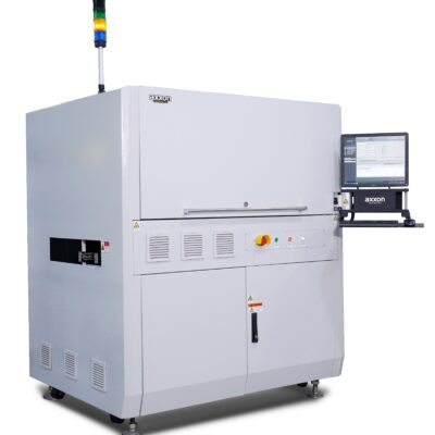
The steps below outline how to select, integrate, and verify an LED curing station, with reference to equipment such as the AUV-E150 LED UV curing oven from Axxonauto as an example.
What Should Be Confirmed Before Installing UV LED Curing Systems?
Before installation, three decisions should be locked: where curing sits in the assembly sequence, which wavelength the material requires, and whether the workpiece geometry allows direct light access.
Wavelength is the first filter. LED sources emit within narrow bands—commonly 365 nm, 395 nm, or 405 nm—and a formulation designed for one band may cure poorly under another. The material supplier’s photoinitiator data should determine the primary wavelength, not the equipment’s default configuration.
Line position affects both handling and exposure. Curing after soldering or cleaning may require conveyor integration, while curing before electrical testing may require tighter coordination with upstream dispensing. The station should not create unnecessary board transfers or obstruct downstream inspection.
Optical access is often underestimated. Components can cast shadows that block LED light from reaching adhesive in recesses or beneath overhangs. If shadowed areas cannot be eliminated by repositioning, a dual-cure material or a secondary curing step may be needed rather than simply increasing lamp power.
How to Integrate a High Power UV Curing LED System Step by Step
The following sequence reflects a practical integration workflow for an inline LED curing oven.
Map the cure window from material data. Record the recommended wavelength, minimum irradiance, and exposure time from the adhesive or coating supplier. Do not substitute a stronger lamp for a missing wavelength match.
Confirm workpiece clearance and conveyor compatibility. Check board width, conveyor height, and top clearance against the oven’s specified dimensions. The AUV-E150, for example, supports a conveyor width of 50–450 mm and a conveyor height of 890–960 mm.
Set lamp height and measure irradiance at the board surface. LED intensity falls with distance. The AUV-E150 specifies 1200 mW/cm² at 40 mm from the emitting surface, with an adjustable working height of 30–100 mm. Measure at the actual production distance, not the datasheet reference point.
Establish conveyor speed against exposure time. The same oven lists a transport speed range of 0.3–3.2 m/min. Calculate dwell time under the lamp and compare it with the material’s required exposure.
Run a cure-quality trial on representative boards. Test adhesion, surface tack, coating integrity, or bond strength depending on the application. Adjust speed and intensity within the validated window.
Connect the curing station to line controls. Confirm SMEMA communication, board-presence signals, and safety interlocks before releasing the station for routine production.
How to Match Wavelength and Irradiance to the Application
Not every UV-curable material suits every LED wavelength. The table below provides a starting point for matching common electronics applications to UV LED curing systems.
| Application | Typical LED wavelength | Key process check |
| Conformal coating protection | 365 nm or 395 nm | Surface cure and through-cure; shadowed areas under components |
| Adhesive bonding (small dots) | 365 nm or 405 nm | Bond strength and placement accuracy |
| Potting / encapsulation | 365 nm | Depth of cure and thermal exposure |
| Inks and marking | 395 nm or 405 nm | Surface hardness and adhesion |
Final selection should always be confirmed by a cure trial with the actual material, thickness, and substrate—not by wavelength alone.
What Should Be Validated Before Releasing the Curing Station?
Validation should confirm that the integrated station produces the required cure under production conditions, not only during a demonstration.
Acceptance criteria should be defined before trials begin: adhesion strength, surface cure, coating continuity, bond performance, or electrical protection depending on the application. Measurements should come from representative boards, including worst-case geometries such as tall components or shadowed areas.
The curing station should also be checked for safety: UV shielding, interlocks, and warning labels must be functional, and operators should be trained on isolation procedures before opening the curing area for service.
Maintenance planning protects long-term stability. LED output monitoring, optical surface cleaning, conveyor alignment, and cooling-system checks should be scheduled according to the manufacturer’s guidance. Any change in material formulation, lamp wavelength, or conveyor speed may require partial or full revalidation.
FAQs
What wavelength should I choose for UV LED curing systems?
The wavelength should follow the photoinitiator system in the adhesive, ink, or coating. 365 nm, 395 nm, and 405 nm are common LED options, but material supplier data and a cure trial should determine the final choice.
Can a high power UV curing LED system cure thick or filled materials?
LED intensity can be high, but cure depth depends on material transmission, filler content, and pigment loading. Thick or opaque materials may require longer exposure, higher irradiance, or a dual-cure formulation.
How does conveyor speed affect UV LED curing?
Conveyor speed determines dwell time under the lamp. If speed increases without a corresponding increase in intensity, the material may receive insufficient energy. Speed and irradiance should be validated together.
How often should UV LED curing systems be verified?
Verification frequency depends on production intensity and material sensitivity. At minimum, irradiance and conveyor speed should be checked after lamp replacement, optical cleaning, or any change in material or board design.
How Can UV Curing Equipment Be Evaluated for Automated Manufacturing?
Assessment should cover curing capability, lamp options, shielding, line-control compatibility, maintenance requirements, and operating costs. Axxonauto can be included in supplier research, with technical suitability confirmed through documentation and production-representative trials.
