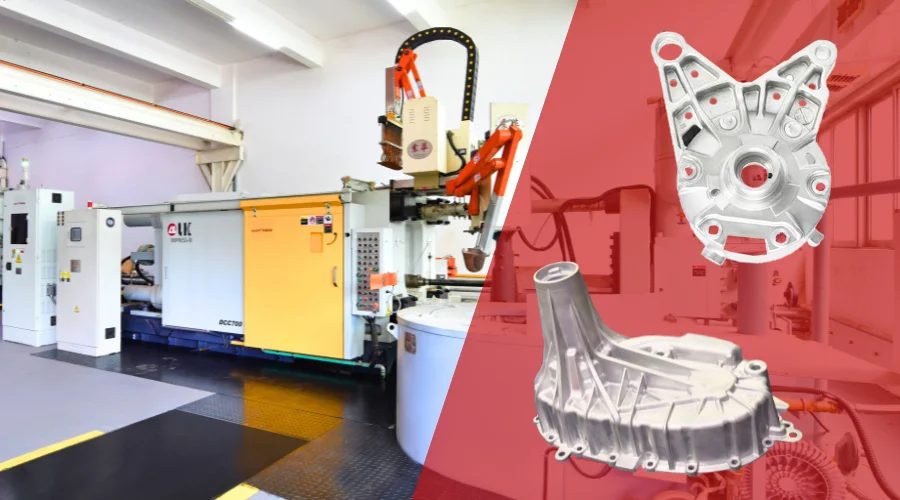
On the busy workshop floor, a rejected part is rarely just a cosmetic inconvenience. When an operator pulls a flawed component from the machine, reacting with endless deburring, trimming, or polishing only hides the underlying failure.
To permanently resolve aluminium die casting defects, technicians and floor engineers must adopt a rigorous troubleshooting mindset. That means moving beyond quick surface fixes and treating every defect as actionable operational evidence—asking precisely where the flaw appears and what the molten metal was experiencing at that exact moment of injection, filling, and cooling.
Mapping the Defect Location Before Changing Machine Settings
Before adjusting injection speeds or metal temperatures, use the physical location of the defect as your primary diagnostic tool. A recurring flaw in the exact same region of a casting reveals a specific failure during a distinct stage of filling or cooling.
Part geometry heavily influences this dynamic: thin sections lose heat rapidly and risk premature freezing, while thick masses cool at a different rate than surrounding material. Recognizing whether a problem stems from machine parameters, tooling wear, or component design prevents blind trial-and-error adjustments on the production line.
Porosity Troubleshooting: Distinguishing Gas From Shrinkage
Porosity requires an internal inspection rather than an external judgment. On the shop floor, it is vital to separate gas porosity from shrinkage porosity because their mechanical origins and corrective paths differ significantly.
Gas Porosity: Typically manifests as smooth-walled voids caused by trapped air, poor venting, turbulent metal movement, or excessive die lubricant. Technicians should inspect gate and vent designs, reduce excessive injection turbulence, and monitor lubricant application rates. Vacuum-assisted casting can also alleviate trapped gas issues.
Shrinkage Porosity: Appears as irregular voids caused by metal contraction during cooling, heavily concentrated in thicker, slower-cooling zones. This requires evaluating local cooling channels and thermal balance rather than altering gas evacuation.
In addition to visual inspection, non-destructive testing can provide a clearer picture of internal aluminium die casting defects that remain invisible on the external surface. X-ray or computed tomography inspection can help identify the size, distribution, and location of internal voids, allowing engineers to correlate defect patterns with specific process conditions. This evidence-based approach reduces unnecessary parameter changes and makes corrective actions more targeted.
While post-casting impregnation or machining can salvage parts, they do not correct the root process variables that generated the voids in the first place.
Fixing Flow and Filling Issues: Cold Shuts and Misruns
Surface-flow irregularities point directly to how the cavity fills, yet cold shuts and misruns require completely different shop-floor interventions.
Cold Shuts: Occur when separate streams of molten aluminium fail to fuse cleanly, leaving a weak structural line. This is often triggered by low metal or die temperatures causing premature solidification, or by insufficient injection pressure. Technicians should examine how advancing metal fronts meet and evaluate gate design.
Misruns: Represent a more severe filling failure where sections of the cavity remain completely unfilled due to inadequate injection pressure, low metal temperature, or complex thin-wall geometry. Fixing a misrun requires ensuring sufficient metal volume reaches the target area before solidification sets in, demanding a comprehensive review of runner layouts and injection speeds.
When filling defects repeatedly occur in the same cavity region, technicians should compare actual machine data against the intended process window rather than relying solely on operator adjustments. Injection velocity curves, pressure profiles, metal temperature, and die temperature can reveal whether the problem is developing during initial filling or the final intensification stage. Combining these measurements with mold-flow simulation can help identify restricted passages and dead zones that contribute to recurring aluminium die casting defects.
Tooling and Clamping Inspections: Tackling Flash and Soldering
When excess metal or unwanted bonding occurs, the fault usually lies with the tooling or thermal management rather than the raw material itself.
Flash: Excess metal escaping along the parting line or around core slides signals a mechanical breakdown. Excessive injection pressure, worn-out die gaps, or insufficient clamping force allowing die halves to separate under pressure are the primary culprits. Regular die maintenance and clamping verification are mandatory.
Soldering (Sticking): Happens when molten aluminium physically bonds to the die surface, tearing the casting or damaging the tool. High metal temperatures, inadequate release-agent coverage, and rough die surfaces escalate this risk. Operators must polish affected tool zones and optimize spray parameters without over-lubricating, as excess vaporized spray creates new gas defects.
Managing Thermal Stresses: Cracks and Sink Marks
Thermal contraction and uneven cooling are the ultimate drivers behind structural cracking and surface depressions. Hot cracking develops during final solidification when contraction creates high stress that brittle or weak matrix areas cannot accommodate. Conversely, sink marks emerge as surface depressions where localized shrinkage lacks sufficient feed material.
Cooling-system performance should therefore be evaluated whenever cracks or sink marks appear repeatedly in the same region. Blocked cooling passages, inconsistent coolant flow, or poorly balanced thermal circuits can create localized hot spots that remain molten longer than surrounding sections. Reviewing thermal imaging, cooling-channel condition, and cycle-time stability can help technicians determine whether the defect originates from inadequate heat extraction rather than from injection parameters alone.
Correcting these issues on the floor requires stabilizing cooling channels, adjusting local wall thickness, and introducing proper fillets during redesign stages to eliminate stress concentrators.
Converting Corrective Actions Into a Repeatable Standard
Effective shop-floor troubleshooting does not stop at making one acceptable batch. HordRT’s manufacturing approach emphasizes that a sustainable remedy bridges tooling condition, process control, and secondary manufacturing.
Technicians must document successful parameter changes, verify tooling health, and ensure that the root cause of aluminium die casting defects is permanently engineered out of the workflow, preventing recurring rejects in future production runs.
